Steps
Categories
J201.pdf Size:851K fairchildsemi. J201 MMBFJ201J202 MMBFJ202GSTO-92GS SOT-23 NOTE: Source & DrainDD are interchangeableMark: 62P / 62QN-Channel General Purpose AmplifierThis device is designed primarily for low level audio and generalpurpose.
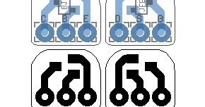
- Jed Fet - J201 SMD to TO92 JFet The TO92 J201 transistor is sparse in existence, and because of that their price has skyrocketed. The sad reality is that you are now highly likely to think you've ordered legit ones from abroad, but when they land they are faked. As pedal builders thats bad news because so many pedals use them.
- Q1 J201 MMBFJ201 SOT-23 JFET N-CHANNEL TRANSISTOR J201 SMD VOLUME 100k-A 100K OHM AUDIO POTENTIOMETER. You can use either through-hole or SMD transistors. The PCB is designed for JFET transistors (J201, 2N5457, 2N5458, MPF102.) with the pinout as shown on the following figure. GENERAL DESCRIPTION OF COMPONENTS.
- J201 JFET N-Channel Amplifier Transistor JavaScript seems to be disabled in your browser. For the best experience on our site, be sure to turn on Javascript in your browser.
Designators and components Step 3 of 5
J201 Smd Adapter

BRIEF INTRODUCTION FOR JFET PREAMPLIFIER DESIGN
In the circuit, the value of R1 represents the input impedance. For guitar applications, 1 MOhm is a common choice. You can also use 2.2 MOhm or even 10 MOhm, you guitar will become brighter; however the noise will be higher. The resistance R2 attenuates the high frequency (in combination with C1), you can use 33k or 64k Ohm. R2 resistor is optional; you can omit it by placing a jumper. The capacitor C1 attenuates the high frequency. You can use from 100pF to 330pF to make the sound less bright. By placing C2, you can obtain all the possible gain of the transistor. Finally, C3 is the output capacitor, it blocks the low frequency signal, you can increase the value to let pass more low frequency signal. Capacitors C1 and C2 are optional; however you need to place C3.
The values of Rs and Rd define the gain and bias of the preamplifier. In class A amplifier operation, the output signal needs to swing from V+ and GND. For clean audio applications, it is recommend set the bias point at half value of +V. For example, if you use 9V power supply, set the bias at 4.5V. However, for guitar applications, it is common to add some harmonic content to the output signal. In this case, you can set the bias point closer to GND or V+ and let the signal saturate easier. If you set the bias point below 4.5V, the saturation will produce hard clipping. If you set the bias point above 4.5V, the saturation will be softer and smoother (tube sounding). By placing trimmers on the PCB, you can easily adjust the preamplifier behavior. The bias voltage can be measured by a voltmeter over the pad Rd on the PCB. You can also obtain the voltage Vs by measuring on the pad Rs.
There is much information about FET guitar preamplifiers out there, here a couple of great references:
http://www.till.com/articles/GuitarPreamp/
http://www.runoffgroove.com/fetzervalve.html
COMPONENT LIST

Find some examples in the following table, however feel free to experiment and create your own preamplifier.
You can use n-type transistors (through-hole or SMD) such as 2N5457, J201, 2N5458 or MPF102.
The value '-' means that you dont need to place anything.
If you use a filtered power supply and the circuit still presents hiss noise it maybe come from the trimmers, you can substitute them for better ones or use regular resistors.
J201 Smd Adapter
The following components corresponds with the FETZER preamplifier:
PCB JFET Preamp DIY PCB
C1 220p 220PF 50V CERAMIC DISC CAPACITOR
C3 47n 47NF 100V 5% POLYESTER FILM BOX TYPE CAPACITOR
C4 100u 100UF 35V ELECTROLYTIC CAPACITOR 6X11MM
R1 1M 1M OHM 1/4W 1% METAL FILM RESISTOR
R2 33k 33K OHM 1/4W 1% METAL FILM RESISTOR
Rd 50k 50k TRIMMER POTENTIOMETER
Rs 10k 10K TRIMMER POTENTIOMETER
Q1 J201 MMBFJ201 SOT-23 JFET N-CHANNEL TRANSISTOR J201 SMD
VOLUME 100k-A 100K OHM AUDIO POTENTIOMETER
TRANSISTOR
You can use either through-hole or SMD transistors. The PCB is designed for JFET transistors (J201, 2N5457, 2N5458, MPF102..) with the pinout as shown on the following figure.
PCB
GENERAL DESCRIPTION OF COMPONENTS
Resistors
The resistors should be ¼ Watt metal type. You can either use a multimeter or the color bands to obtain their values. Resistors do not have polarity, you can place them in any direction.
Electrolytic capacitors
Electrolytic capacitors have their value printed on them. The negative polarity pin is indicated by a white strip along the can. They also have a longer leg indicating the positive pin. The maximum voltage rating never can be exceeded, make sure you are using at least double voltage rating than your power supply. Corrupt video repair tool for mac. For example, if you are using a 9V power supply, use a electrolytic capacitor with at least 18V maximum voltage rating.
Polyester capacitors
The polyester capacitors have their value marked with three numbers. Read as picofarads (pF), the first two are the 1st and 2nd digits and the third is the multiplier code. These capacitors do not have polarity, you can place them in any direction.
Ceramic capacitors
The ceramic capacitors have their value marked with three numbers. Read as picofarads (pF), the first two are the 1st and 2nd digits and the third is the multiplier code. These capacitors do not have polarity, you can assemble them in any direction.
Transistors
Manual uninstall code composer studio 6 mac. Transistors are three terminals components and their model is printed on them. To indicate the correct orientation, one side of the transistor is flat and the other one is round.
Potentiometers
Potentiometers have their resistance value marked on them. They are marked with A, B or C for logarithmic, linear and reverse logarithmic, respectively.

J201 Smd


J201 Smd
Products
